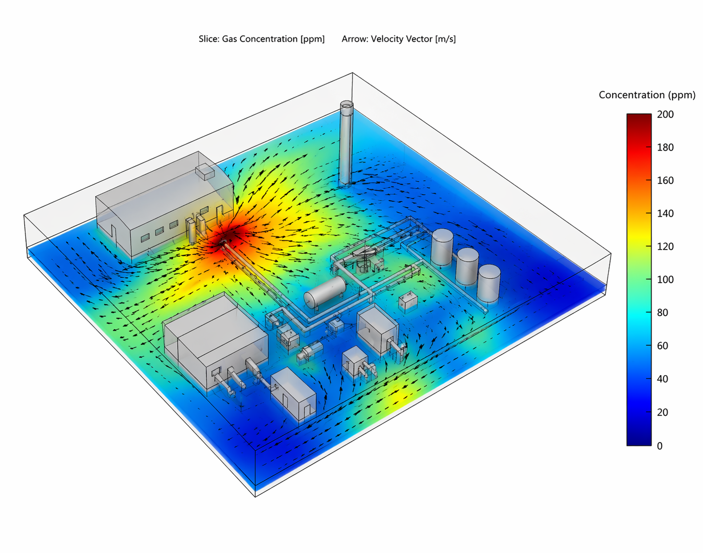
CFD for Toxic Gas Control in Gulf Manufacturing Plants in KSA, Kuwait and Oman
INTRODUCTION
The Gulf’s manufacturing sector—refining, petrochemicals, fertilizer, metals, and specialty chemicals—operates in a uniquely harsh envelope: extreme heat (often >45 °C), high solar loads, coastal humidity, Shamal winds, and intermittent dust events. In this context, Computational Fluid Dynamics (CFD) simulation has become a high-leverage tool to design, verify, and continuously optimize systems for toxic-gas removal and exposure control—well beyond what rules-of-thumb or 1-D calculations can provide.
Why CFD Analysis here, and why now?
- Complex physics: Buoyant plumes from hot equipment, heavy-gas pooling (e.g., H₂S, Cl₂), wind channeling around congested pipe racks, and thermally stratified indoor air are hard to predict without 3-D transient modeling.
- High stakes: Worker exposure limits, shelter-in-place (SIP) decisions, and offsite impact all depend on spatial and temporal concentration fields, not just averages.
- Cost pressure: Fan horsepower, scrubber sizing, and duct layouts are major OPEX/CAPEX drivers; CFD pinpoints where capacity is truly needed.
-
Typical Gulf use cases
Indoor source capture & dilution
Optimize hood capture velocities and canopy shapes over tanks, mixers, and loading points.
Balance make-up air and extraction to avoid dead zones caused by strong roof jets or equipment heat.
Verify compliance with target time-weighted average (TWA) and short-term exposure limit (STEL) isosurfaces at breathing height (≈1.5 m).
Outdoor dispersion in process areas
Predict heavier-than-air gas accumulation (H₂S, SO₂, Cl₂) in cable trenches, pits, sumps, or low courtyards.
Evaluate wind-driven re-entrainment into air intakes; place and shield intakes accordingly.
Test fence-line concentration under seasonal wind roses and stability classes.
Emergency scenarios & SIP
Abatement system design
Scrubber inlets: ensure uniform velocity/contaminant distribution to prevent channeling.
Stack design: momentum vs. buoyancy trade-offs, exit temperature, and minimal downwash/recirculation near occupied decks.
Confined spaces & maintenance
Modeling notes that matter in the Gulf
Thermal environment: Include solar gains on roofs/walls and equipment heat loads; buoyancy drives stratification and recirculation that can trap gases under canopies.
Turbulence models: Start with realizable k-ε for robustness; use k-ω SST near separation/attachment; reserve LES/DES for critical transient studies (e.g., rapid releases, vortex-driven re-entrainment).
Species & reactions: Use multi-species transport; add simplified reaction or absorption source terms for reactive or scrubbed species (e.g., SO₂, NH₃).
Density effects: Enable full compressible/buoyancy-correct density for heavy or light gases (ideal-gas or real-gas where needed).
Boundary conditions: Calibrate ABL (atmospheric boundary layer) profiles to site roughness (desert vs. industrial forest), with seasonal stability (Pasquill-Gifford) and Shamal statistics.
Meshing strategy: Local refinement along jet cores, around intakes/hood lips, and inside cable trenches. Check y+ for wall models; capture near-floor pooling.
Validation: Compare to portable electrochemical sensor arrays, PID readings, or fence-line FTIR; use smoke/fog visual tests indoors to confirm recirculation predictions.
Design levers CFD Modelling helps optimize
Hood geometry & placement: Lip shapes, side curtains, and booth enclosures—find the minimum flow that achieves capture efficiency across tasks.
Supply-exhaust balance: Pressure zoning to prevent cross-contamination between process rooms and corridors/SIP rooms.
Intake/stack siting: Elevation, orientation, rain caps, and velocity ratio to minimize downwash and short-circuiting.
Air changes & energy: Right-size fans and VFD control logic; reduce over-ventilation without sacrificing safety.
Sensor strategy: Optimal spacing and height for H₂S/Cl₂/NH₃ detectors to catch pooling and early leaks while minimizing false alarms.
KPIs to track (and design to)
Peak & 95th-percentile concentrations at breathing height in occupied zones.
Capture efficiency (%) at source hoods across the operating envelope.
Time to threshold (e.g., to reach 10 ppm H₂S) at specified receptors.
Energy intensity (kWh per m³/s exhausted) and specific removal cost (USD per kg pollutant removed).
Resilience metrics: Acceptable exposure under fan or power failure scenarios.
Quick checklist for teams
Do we model heat and solar loads explicitly?
Are heavy-gas pooling zones (pits, trenches) meshed and instrumented?
Have we stress-tested intake/stack siting against seasonal winds?
Do sensor locations align with predicted concentration hotspots?
Is there a dust-storm/blackout ventilation mode with fail-safe logic?
Have we validated at least one scenario with field measurements?